Source intakeImage, project type and visible constraints
From image to build plan
Give us the image.
See the build logic.
Explore how an approved visual can become an engineering starting point: visible forms are organized into components, an exploded view, an assembly sequence and a draft bill of materials.
AI-assisted first pass+Engineer-controlled release
F
Image-to-Build WorkspaceRF-DEMO-001 / Specialty Display
Ready for inputInteractive Demo
Visual readForms, interfaces and likely materials
Component mapInitial modules and part relationships
Exploded viewSuggested build and shipping separation
Assembly planSequence, draft BOM and review questions
Engineering preview progress0%
Customer inputFORMERA sample / installed retail display
Preview stays in this browser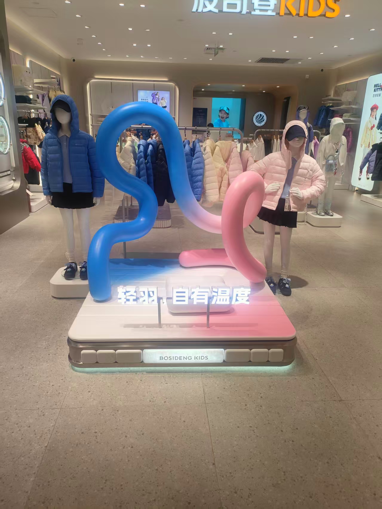 A-01 · FRP formA-02 · FRP formB-01 · plinthL-01 · light/sign
Engineering outputWaiting for component analysis
Rev 0 · not released+
Start the analysis to generate a structured preview.
The first pass will identify likely components and expose the questions an engineer must resolve before quotation or production.
Draft bill of materials
What the system organizes.
Each visible element becomes a reviewable work package. Material, process, quantity and confidence stay connected to the source image and later revisions.
PartComponentLikely material / processQtyReview flag
A-01Sculptural shell AFRP · painted gradient1Finish sample
A-02Sculptural shell BFRP · painted gradient1Finish sample
S-01Internal support frameWelded steel · powder coat1Engineer review
B-01Display plinthPlywood / MDF · HPL + paint1Dimensions needed
L-01Lighting + sign moduleLED · acrylic · wiring1UL path review
K-01Hardware kitBolts · plates · locator pins1 setDraft
What this demo is
An interactive illustration of FORMERA's intended image-to-engineering workflow.
What it is notAn approved production drawing, structural calculation, final BOM or binding quotation. Formal release requires project inputs and engineer review.